YA-µCP
a PIC and AVR Programmer!
YA-µCP = Yet Another Microcontroller Programmer.Intro
The goal of the YA-µCP is to allow electronic hobbyists the ability to program two of the most popular microcontrollers in the market, the PIC by Microchip and the AVR by ATMEL with one simple and easy to carry device.
Microcontrollers are everywhere. Due to their low cost, availability and flexibility they are very attractive for electronic hobbyists, especially hackers. Both the AVR and the PIC have their pros and cons. Merging the 2 microcontrollers by providing an AVR and PIC programmer in a single device will help expose people the two architectures, allowing them to decide on their own which microcontroller they like best.
The following images will show the top and bottom 3D renders of board. These images were created with Eagle 3D and POV-Ray.
Top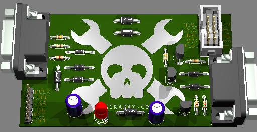
Bottom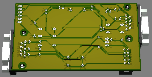
Details
The YA-μCP has been designed as an entry to the Hack A Day “design challenge” which requires certain specifications to be met, such as implementation of their logo, the board size (restricted to 3.5” x 2”), etc. Due to these restrictions, I decided to implement two ISP (in system programming) in to one simple, small design.
Due to the lack of time, I decided to use the well known ICSP only serial port design based on the popular JDM circuit for the PIC and the STK Serial port circuit for the AVR eliminating the need for new software and extensive test. The PICs can easily be programmed using ICPROG and WinPIC, while the AVRs can be programmed using PonyProg.
There is no need to provide external power to the programmer, increasing its portability and providing a more cost effective design. The AVR section uses the 2x5 ICSP connector setup and the PIC section has the 6 pins, which enables direct connection to breadboards.
The programmer communicates with the computer through the serial port. Additionally, the compact design of my board will also support simultaneous use of the two programmers.
The board consists of two layers. The bottom layer of the PCB includes the routed signals, while the top layer displays the HACK A DAY logo, in order to comply with the contest rules. With this entry, I am also including three logos that had to be made in order to fix the artifacts, which were a result of the enlargement of the website’s logo.
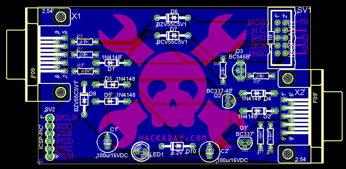
The following images will show the top and bottom layers of the routed board. These images were screen shots that were captured while using Eagle.
Top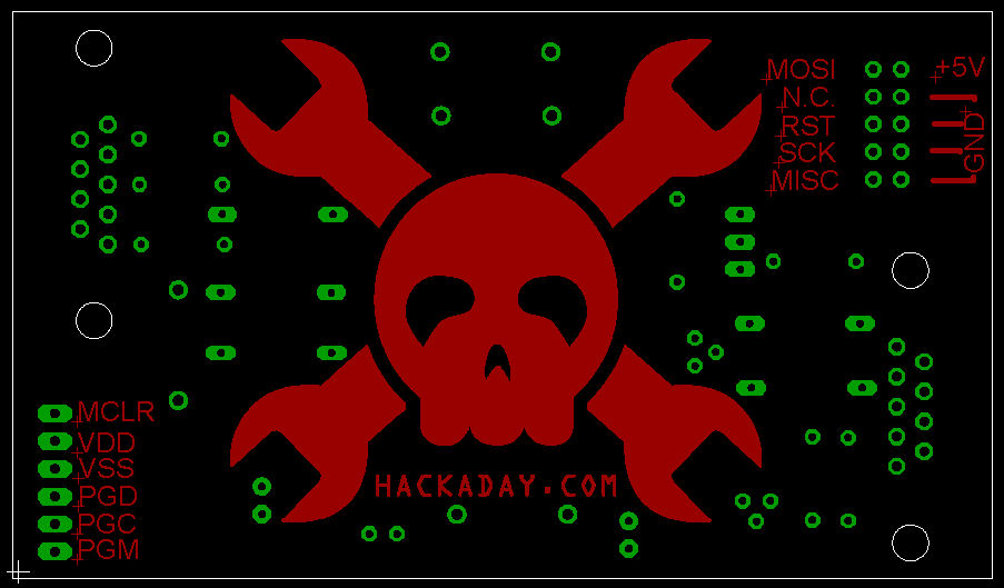
Bottom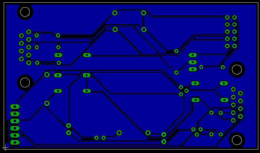
Part List
| Part | Value | Device | Package | Description |
| C1 | 100u/16VDC | CPOL-USE2.5-7 | E2,5-7 | POLARIZED CAPACITOR |
| C2 | 100u/16VDC | CPOL-USE2.5-7 | E2,5-7 | POLARIZED CAPACITOR |
| D1 | 1N4148 | 1N4148 | DO35-10 | DIODE |
| D2 | 1N4148 | 1N4148 | DO35-10 | DIODE |
| D3 | 1N4148 | 1N4148 | DO35-10 | DIODE |
| D4 | 1N4148 | 1N4148 | DO35-10 | DIODE |
| D5 | 1N4148 | 1N4148 | DO35-10 | DIODE |
| D6 | BZV55C5V1 | BZV55C5V1 | DO41Z10 | Z DIODE |
| D7 | BCV55C5V1 | BZV55C5V1 | DO41Z10 | Z DIODE |
| D8 | BZV55C5V1 | BZV55C5V1 | DO41Z10 | Z DIODE |
| D10 | 6.2V | Zener Diode | DO41Z10 | Z DIODE |
| LED1 | LED5MM | LED5MM | LED | |
| Q1 | BC337 | BC337 | SOT54A | NPN TRANSISTOR |
| Q2 | BC337-40 | BC337 | SOT54A | NPN TRANSISTOR |
| Q3 | BC546B | BC546B | TO92-EBC | NPN Transistor |
| R1 | 10K | R-US_0204/7 | 0204/7 | RESISTOR |
| R2 | 4.7K | R-US_0204/7 | 0204/7 | RESISTOR |
| R3 | 4.7K | R-US_0204/7 | 0204/7 | RESISTOR |
| R4 | 33K | R-US_0204/7 | 0204/7 | RESISTOR |
| R5 | 10K | R-US_0204/7 | 0204/7 | RESISTOR |
| R6 | 1.5K | R-US_0204/7 | 0204/7 | RESISTOR |
| R7 | 10K | R-US_0204/7 | 0204/7 | RESISTOR |
| SV1 | ICSP-AVR | ML10 | ML10 | HARTING |
| SV2 | ICSP-PIC | MA06-1 | MA06-1 | PIN HEADER |
| X1 | Serial Fem | F09H | F09H | SUB-D |
| X2 | Serial Fem | F09H | F09H | SUB-D |
Assembly
As for assembly, I would recommend starting with the AVR section of the programmer. First install the DB9 female connector, then, proceed with the pin header and then the rest of the components. After testing repeat the same with the Pic section. The schematics could also be distributed to help locate the components and the values. If the board is built using the SILK screen, the assembly will be easier; however, the price of manufacturing will increase.
The following screen capture is of the board with all the layers turned on:
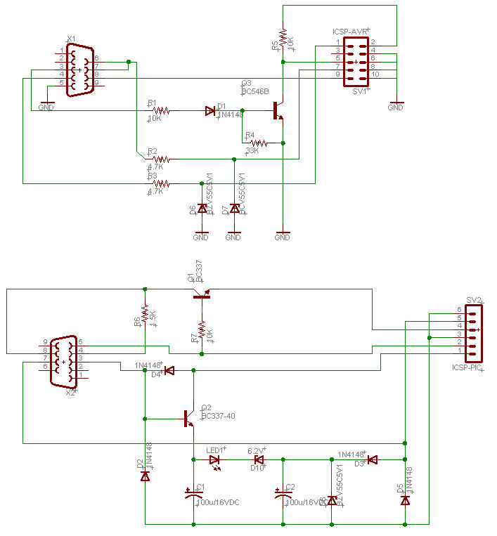
Schematic:
Supported devices (some others may also work):
AVR:
| AT90S1200 | AT90S4434 | AT90S2333 | ATmega8 | ATmega161 |
| AT90S2313 | AT90S8515 | AT90S4433 | ATmega16 | ATmega163 |
| AT90S2323 | AT90S8535 | AT90S4434 | ATmega64 | ATmega323 |
| AT90S2343 | AT90S2323 | AT90S8535 | ATmega103 | ATtiny12 |
| AT90S4414 | AT90S2343 | AT90S8534 | ATmega128 | ATtiny15 |
PIC:
| 12C508 | 12F629 | 16C66 | 16C77 | 16C712 | 16C781 | 16F77 | 16F676 | 16F876 | 18F452 |
| 12C508A | 12F675 | 16C67 | 16C505 | 16C715 | 16C782 | 16F83 | 16F818 | 16F876A | 18F458 |
| 12C509 | 16C61 | 16C71 | 16C620 | 16C716 | 16C923 | 16F84 | 16F819 | 16F877 | 18F1320 |
| 12C509A | 16C62A | 16C72 | 16C620A | 16C717 | 16C924 | 16F84A | 16F870 | 16F877A | 18F2320 |
| 12C671 | 16C62B | 16C72A | 16C621 | 16C745 | 16CE623 | 16F87 | 16F871 | 18F242 | 18F4320 |
| 12C672 |
16C63 | 16C73A | 16C621A | 16C765 | 16CE624 | 16F88 | 16F872 | 18F248 | 18F4539 |
| 12CE518 | 16C63A | 16C73B | 16C622 | 16C770 | 16CE625 | 16F627 | 16F873 | 18F252 | 18F6620 |
| 12CE519 | 16C64A | 16C74A | 16C622A | 16C771 | 16F73 | 16F628 | 16F873A | 18F258 | 18F6720 |
| 12CE673 | 16C65A | 16C74B | 16C710 | 16C773 | 16F74 | 16F628A | 16F874 | 18F442 | 18F8620 |
| 12CE674 | 16C65B | 16C76 | 16C711 | 16C774 | 16F76 | 16F630 | 16F874A | 18F448 | 18F8720 |
NOTE:
This project hasn't been tested/build, but “it should work” since the schematics were taken from designs that work; the layout was modyfied to meet the design challenge rules.References:
Olimex.com | Source of the original schematics.CadSoft.de | PCB and Schematic software.
Eagle3D | Creates 3D Pov file.
POV-Ray | Renders the POV file.
SparkFun.com | Eagle tutorial.
Instructables.com | A very good Eagle tutorial.